|
|
|
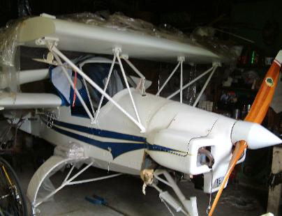
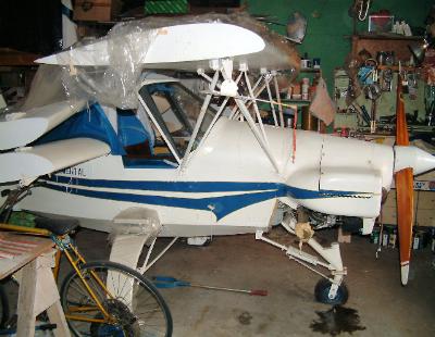
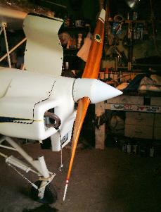
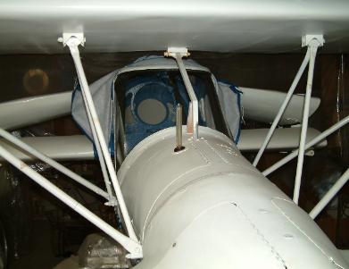
Above photos show starboard (R.H.) view, front wing struts, laminated mahogany / glass
main gear, fiberglass moulded engine cowling, nose gear, enclosed canopy, custom prop.
Note the pivotable air speed pitot tube on R.H. Side of the wing center section, and the
Piper Cub vertical style fuel tank stick meter just forward of the windshield. The forward
wing outer panels have been removed from the hinges, but the aft wing outer panels are
shown in their folded position. This aircraft fits sideways in Al's small two car garage.
|
|
|
|
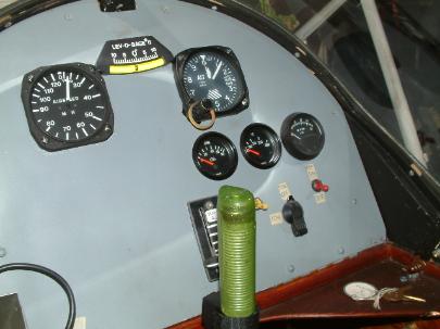
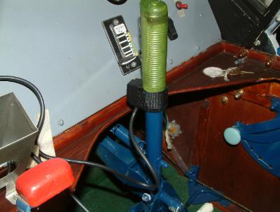
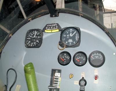
Above photos show a very clean and basic instrument panel. The throttle is the left hand
side red cluster knob and the front wing / rudder control stick is the green handle.
|
|
|
|
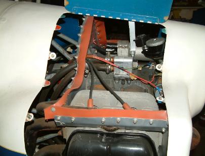
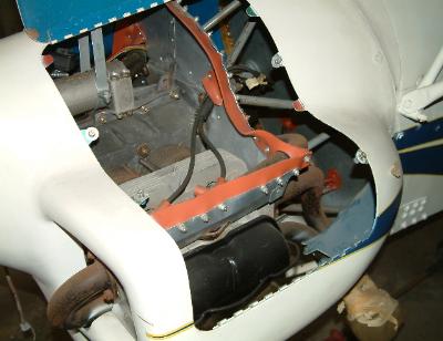
Above photos show the engine cowling with access by duel L.H. and R.H. hinged doors on
the centerline of the aircraft. The converted VW 1800cc engine shown is absolutely new
(despite the years of protected storage) complete with ignition, gear box drive, carbs and
rear magneto. I doubt that it even has 4 - hours of running time. Fully baffled and with a thin
galvanized steel sheet firewall on the bulkhead behind the engine. The tubular engine mount
can also be seen. Absolutely clean.
.
|
|
|
|
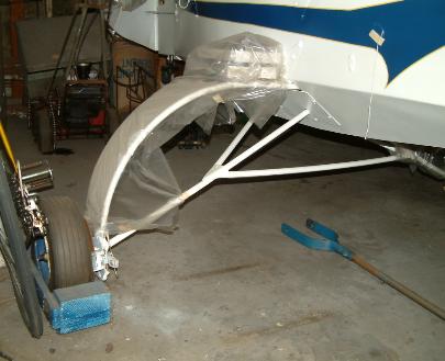
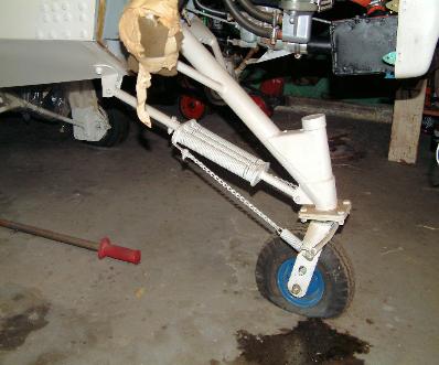
Above photos show the Mahogany / glass laminated main landing leaf with what was
viewed as 8 inch wheels with hydraulic disk brakes. Tubular steel bracing also attaches
internal into the fuselage through cover plates. The nose gear is self-swiveling with tension
spring shocks, shown, and anti-shimmy springs. The wheel appears to be a 6 inch size. Al
custom designed these also. Al was a Senior Design Engineer for the Douglas Aircraft
Company while he was building this aircraft. All welding was done by certified aircraft
welders. After nearly 18 years, there is still air in the main gear tires, gone from the nose
wheel tire.
|
|
|
|
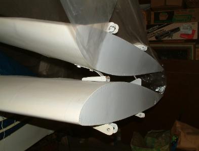
Left photo above shows the aft wing hinge arrangement with the outer wing panel folded.
There was no dust on the wing when the plastic sheeting was removed for taking this
photo. The aft wing center section also has full length trim tabs for up and down in-flight
operation. The right photo above shows another view of Al's custom handy work....his
custom made propeller.
|
|
|
|
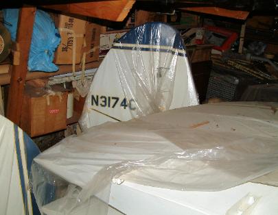
A hard to get at view to take the photo of the
rudder is shown above left.
It appears to be a 40% fixed vertical fin and
60% rudder with a rudder counter-balance at
the top. An excellent combination for effective
rudder control. The aft wing is also shown
folded under the protective plastic sheeting.
Just part of a forward wing tip panel can be
seen on the floor to the extreme lower left.
The FAA "N" number 3174C was issued
October 01,1991 and cancelled on
May 18, 2007
|
Above right is another instrument panel
photo. From left clock-wise:
Airspeed indicator, "Lev-o-gage II" ball side
slip gage, Engine gages - RPM,
Temperature, Oil pressure, and Electrical
switches - Magneto On/off master, Mag.
check on/off, master switch.
The lower center vertical meter is the
forward wing angle of attack indicator from
-3 degrees to +12 degrees.
There is also a magnetic compass, just out
of the picture at the top, above the ball side
slip gage.
|
|
|
The photo to the left shows a straight on
shot from the engine cowling to the
windshield / canopy.
Note the single structural square tube for
moving the forward wing to change the angle
of attack (being held up by a stick).
Hinged access doors to the fuel tank and
instruments are also evident.
Uniquely designed brackets bolted to the
main spar (spar not seen) of the forward
wing are also evident to the trained eye.
|

