Biplane Center of Gravity Limits on MAC (Mean Aerodynamic Chord)
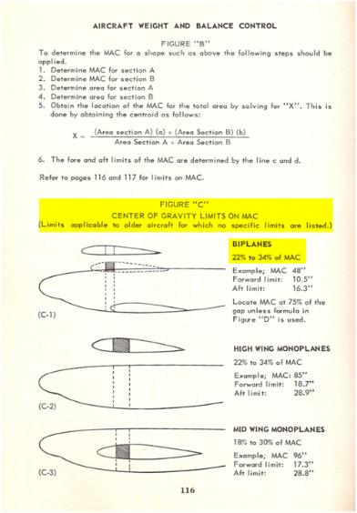
**as applicable to older aircraft for which no specific limits are listed
by Richard W. Fraser
The double asterisk sentence above relates to a direct quotation from part of a title within a very important section
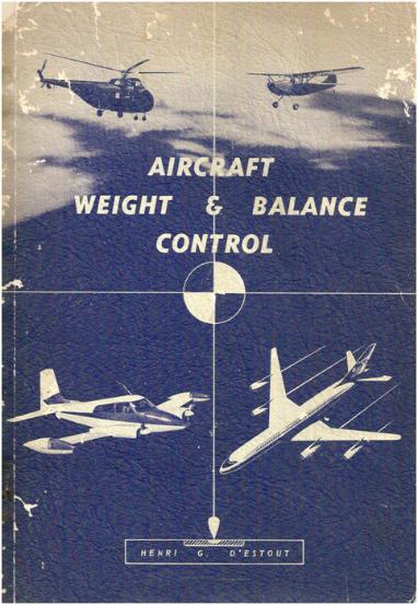
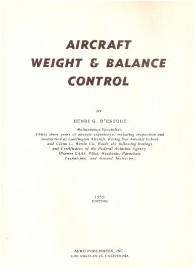
from the book “AIRCRAFT WEIGHT & BALANCE CONTROL” by
Henri G. D ’estout, 1959 edition, published by AERO PUBLISHERS, INC., LOS ANGELES 26, CALIFORNIA (no
longer in business), Figure “C”, page 116 in the Appendix to be exact.
It is evident that most of the early aircraft that were developed, back then (back then means those of you reading
this were not born yet), did not contain the fore and aft C.G. limits. Mr. D ‘estout had 33 years aircraft experience,
as stated in his book, which means that prior to the 1959 edition, less his 33 years aircraft experience, would make
the date 1926 when he started in the business.
Mr. Mignet finished his first HM 1-1 Monoplane glider in 1912 and his HM-8 in 1928. That puts Henri in the same
“forgetful league” as the rest of the early designer / builders. Forgetful only because some of us today are now
demanding fore and aft C.G. limits where it is a pretty good chance that this was not the requirement in that part of
the century. Remember the highlighted statement above.
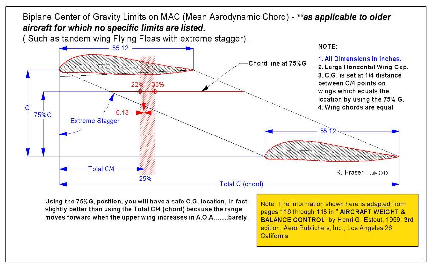
Anyway, I have worked out some geometry for extreme staggered Biplanes, ala tandem wings or Flying Fleas,
whatever you may want to call them, based upon Mr. D ‘estout’s book.
Please refer to Figure 1.
Before you try to figure out Figure 1, you should familiarize yourself with the other pages copied from the book,
mainly the books page 116, Figure “C” for the biplane C.G. Limits.
Now pay attention: In the book the MAC is shown not in the correct location. In fact, it is not the MAC. The chord
shown at a 75% gap position, however is what you use. And, it also works well on highly staggered tandem
wings. Now that’s amazing? Not much guess work here.
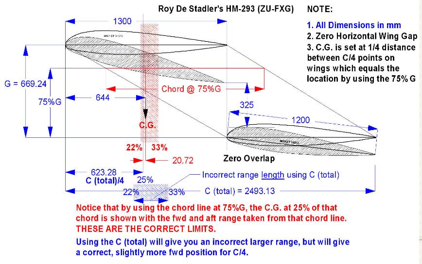
Limits laid out by using the total wing chord “C” length (from the leading edge of the forward wing to the trailing
edge of the aft wing) as shown in Figure 1 work better than when using a no horizontal gap as shown in Figure 2.
Position 22% of C and 33% of C on the chord line at the 75% gap position. There should be your safe C.G. limits in
the correct position for both examples.
Stay with the Figure 1 and Figure 2 examples with horizontal wing positions and the 75%G with total wing chord
measurements as shown and you should have a well balanced airplane in flight
It is also important to remember that even though these limits are listed it is only a good place to start.
Limits always requires testing the aircraft to verify this, even with the same design that was built using the very
same set of plans because there are always building differences between individuals.
Analytically, the above limits should be safe as they were developed from experience some time ago. An
experienced test pilot should be able to tell you if they are comfortable limits. Unfortunately, very few home
builders have an opportunity to have an experienced test pilot to rely on. That is why there is something called
Production Aircraft. Government agencies demand it.
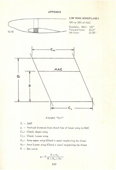
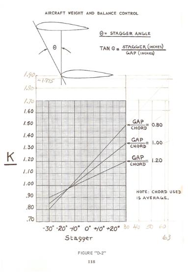
Figures 3 through 7 follow. They are copies of pages from the quoted book of experience.
As errors are found during our sampling, we will continue to revise this unique C.G. Relationship.
Sincerely,
Richard Fraser
|
|
|
Figure 1
|
|
|
Figure 2
|
|
|
Figure 3
|
|
|
Figure 4
|
|
|
Figure 5
|
|
|
Figure 6
|
|
|
Figure 7 - Book appendix page 118, but extrapolated for
higher “K” values
|
|


